I have been wondering how we can show VR view without relying on Facebook. Today I found "VR View for the Web" by Google. Here is how it looks.
By the way, try viewing this post using your mobile. The view works for mobile as well!
For comparison, the VR view by Facebook seems to work only within Facebook's site. On the plus side, the Facebook view has the camera top-down orientation gizmo that I find helpful.
I personally am more comfortable with Google's approach. It feels more open and less intrusive. What do you think? Let us all know in the comments below :)
Wednesday, August 17, 2016
Friday, May 27, 2016
Dungeon Boss Short Videos
Recently I had the privilege to work on short promotional videos for Dungeon Boss, a mobile game by Big Fish Games. Here is the final product.
My involvement was minor, early in the production process and therefore cannot be directly seen in the video. My contribution was lighting the set and recommending ways to texture the set to achieve to look the client wanted. After that texture artists and lighters took over to get the final look seen in the video. Still, I am happy with the final look.
Here is an alternate version with a different opening.
What do you think of the videos? Let me know by commenting below :)
Thursday, September 17, 2015
Rendering Maya nHair Using Mental Ray
In the previous post, we saw how we can create an nHair system in Maya using FiberMesh in ZBrush. In this post, we will see how we can render the nHair system in Maya using Mental Ray and get as render like this.
Before we start, make sure that Mental Ray is loaded and that it is the active renderer. Here is my render at this point.
Here are what happened when we pressed the "Create" button:
There are more things happening behind the scene that we need to understand.
But that's not all. Select your render camera and see the Attribute Editor:
We are particularly interested in the lens shader mia_exposure_simple:
The rendered image looks deceptively alright, but it is actually overly bright because of incorrect gamma value.
The shadow area looks more natural. However, the hair looks grainy and hard. We will now fix this.
I personally find "Unified Sampling" mode make render time much longer than necessary; so I prefer to use "Legacy Sampling Mode" (see Figure 8 right). This mode gives me more control over the quality-render time trade-off. For example:
The hair still has grainy look to it, caused by hair shadow. We will fix this next.
Credit: I learned about hair shadow settings from the article "Set up hair self-shadowing" at Autodesk Knowledge Network. Read this article for more insight behind the values I set above.
Render your scene. My render looks like this.
And that is it! You can now work on your lighting and get a nice hair render.
 |
| nHair system rendered using Mental Ray. |
Before we start, make sure that Mental Ray is loaded and that it is the active renderer. Here is my render at this point.
 |
| Figure 1. Render at the starting point. |
1. Creating Physical Sun and Sky
We are going to light the scene using Mental Ray's Physical Sun and Sky system. (In 3ds Max, the equivalent is the Daylight System.) Creating physical sun and sky is easy:- Open the "Render Settings" dialog.
- Go to "Indirect Lighting" tab (see Figure 2).
- Expand the "Environment" group.
- Click the "Create" button next to "Physical Sun and Sky".
 |
| Figure 2. Creating Physical Sun and Sky. |
- Final Gather is automatically enabled (see Figure 3 left).
- A directional light called "sunDirection" is created (see Figure 3 right).
 |
| Figure 3. Left: Final Gather is enabled. Right: a directional light is created. |
- Let us start by selecting the "sunDirection" light.
- The Attribute Editor shows the parameters of "sunShape" (see Figure 4 left).
- Notice that "sunDirection" light is assigned a mia_physicalsun shader (see Figure 4 left). This is a Mental Ray light shader. It makes the directional light to behave physically correct during rendering.
- Next, click the boxed arrow button on the right of "Light Shader" (see Figure 4 left).
- The Attribute Editor now shows the mia_physicalsun parameters (see Figure 4 middle).
- Notice that there are 5 parameters ("Multiplier", "Haze", "Red-Blue Shift", "Saturation", and "Horizon Height") highlighted in yellow. They are connected to the parameters of the physical sky shader (which we will inspect next). Remember that you can break any of these connections so that the sun shader uses a different parameter from the sky shader.
- Click the "mia_physicalsky1" tab of the Attribute Editor (see Figure 4 right).
- Notice that this shader uses the "sunDirection" light as its "Sun" parameter. This means you can create a light and assign it as the "Sun" of this sky shader.
- Also, experiment setting the value of "Multiplier" to 2.0, then seeing the "mia_physicalsun2" tab. Confirm that "mia_physicalsun2" "Multiplier" value is also 2.0. The same connection applies to 4 other parameters as discussed above.
- Make sure you set the "Multiplier" value back to 1.0 before proceeding.
 |
| Figure 4. More things happening behind the scenes. Middle: Mental Ray physical sun shader. Right: Mental Ray physical sky shader. |
- The physical sky shader, "mia_physicalsky1", is attached as "Environment Shader" (see Figure 5 left).
- Another Mental Ray shader called "mia_exposure_simple1" is attached as "Lens Shader" (see Figure 5 left).
 |
| Figure 5. Mental Ray shaders attached to the camera. Left: the camera shape node. Right: the mia_exposure_simple shader. |
We are particularly interested in the lens shader mia_exposure_simple:
- Click the boxed arrow icon on the right of "Lens Shader". The Attribute Editor will show the parameters for the mia_exposure_simple shader (see Figure 5 right).
- Notice that the "Gamma" value is 2.2.
- Render your scene.
- My render looks like this.
 |
| Figure 6. Rendered image with Gamma value 2.2. |
- Set the "Gamma" value to 1.0.
- Render your scene again.
- My render now looks like this.
 |
| Figure 7. Rendered image with Gamma value 1.0. |
The shadow area looks more natural. However, the hair looks grainy and hard. We will now fix this.
2. Improving Sampling Quality
First, we will improve Mental Ray's sampling quality:- Open "Render Settings" dialog.
- Go to "Quality" tab (see Figure 8).
- Expand "Sampling" section.
- By default, the "Sampling Mode" is "Unified Sampling" and the "Quality" is set to 0.25 (see Figure 8 left).
- Set "Quality" value to 1.0.
- Render your scene.
- The hair should look less grainy now, at the cost of longer render time.
 |
| Figure 8. Mental Ray Sampling parameters. Left: default settings. Right: my personal preference. |
- I set "Min Sample Level" to -1 & "Max Sample Level" to 1 for fast renders.
- I set "Min Sample Level" to 2 & "Max Sample Level" to 3 for high quality renders.
 |
| Figure 9. Rendered image with improved sampling quality. |
3. Improving Hair Shadow
Select the light "sunDirection" and open the Attribute Editor:- Expand the "Shadow" section (see Figure 10 left).
- By default, the light uses ray traced shadows. The render scenes with hair, use depth map shadows instead.
- Check "Use Depth Map Shadows" (see Figure 10 right).
- Set the following parameters:
- "Resolution": 4096;
- "Use Mid Dist": unchecked;
- "Filter Size": 4 (or higher; the higher, the more blurred the shadows are);
- "Bias": 0.05.
 |
| Figure 10. Shadow settings. |
Credit: I learned about hair shadow settings from the article "Set up hair self-shadowing" at Autodesk Knowledge Network. Read this article for more insight behind the values I set above.
Render your scene. My render looks like this.
 |
| Figure 11. Rendered image with improved hair shadows. |
Thursday, August 27, 2015
Creating Maya nHair Using ZBrush FiberMesh
In this post, I will go through how you can export FiberMesh from ZBrush to Maya to render. I will focus on the procedural steps, not the artistic aspect.
To manage expectation, let me point out that the post only covers the creation of the nHair system. At the end of it, you do not get the render above yet. To get that render, you will need to go through this post as well as the rendering post.
In addition, I got excellent tips from Charlie Kim.
Here is how my FiberMesh looks.
Now we are ready to open the curves in Maya.
Next, we will add the imported curves to the nHair system we created earlier.
If we open the Outliner, we can see that Maya created a new group hairSystem1OutputCurves. This is what the nHair system needs to generate hair. The generated hair is in pfxHair1.
Let us take a close look at the generated hair.
Each imported curve actually has multiple hairs (see Figure 9 left). This reason is the default setting of hair system. Here is how you can make sure there is 1 hair for each curve:
Back to our hair, here is how it looks in the viewport and Maya software render.
And that is it! You can now render the hair using your favourite renderer. In the next post, I will cover how to render the hair system using Mental Ray (and how I got this render below).
 |
| Hair rendered in Maya using Mental Ray |
1. Creating FiberMesh Hair in ZBrush
There are tutorials out there that show you how you can create hair using FiberMesh. I recommend going through this video tutorial: "Fibermesh : Zbrush to Maya, Efficient Workflow Pt1 /// ZBRUSH" (it is 15 minute long).In addition, I got excellent tips from Charlie Kim.
 |
| Figure 1. Brush menu. |
- Go to Brush menu; expand FiberMesh section (see Figure 1).
- Set "Preserve Length" to 100.
- This means whatever we do to the Fibers using the active brush, the Fibers will remain the same length.
- I find this is the key setting that makes working with FiberMesh (relatively) easy.
- The "Front Collision Tolerance" enables a collision detection between the Fibers and the head mesh. On the other hand, the collision detection causes the Fibers to look "jittery".
- Further down Brush menu, expand Auto Masking section (see Figure 1).
- "Mask By Polygroups" enables you to affect only the polygroup you start your stroke on. I turn this on and off depending on what I am doing.
- "FiberMesh Mask Curve" determines how much your stroke affects the Fiber along the Fiber strand.
- By default, the mask is maximum at the root. This is why it is impossible to move the root of Fibers. This is also why the tip moves the easiest.
- Change the shape of the curve based on what you are working on.
Here is how my FiberMesh looks.
 |
| Figure 2. Left: screenshot of ZBrush viewport. Right: BPR render. |
2. Exporting FiberMesh to Maya
- Go to Tool menu.
- Make sure you select the SubTool that contains your FiberMesh (see Figure 3).
- Scroll further down to FiberMesh section, "Export Curves."
- Click "Export Curves" button.
- Make sure you save as "Maya Ascii Format (*.ma)" (see Figure 4).
 |
| Figure 3. Tool menu. |
 |
| Figure 4. "Export FiberMesh Curves" dialog. |
3. Creating Hair in Maya using nHair
Before importing the curves, let us create an nHair system first.- Create a plane.
- This plane is just a temporary dummy to create nHair system; we will delete it later.
- Make sure you select "nDynamics" menu set (see Figure 5).
- Click "nHair" > "Create Hair" (see Figure 5).
- Open Outliner.
- Notice that Maya created 4 objects (see Figure 6): hairSystem1, hairSystem1Follicles, pfxHair1, and nucleus1.
- hairSystem1 is where we set parameters to control the look of the hair a well as its dynamic behavior in simulations.
- pfxHair1 is the paint effect that gets rendered.
- nucleus1 is the Nucleus simulation solver.
- In this method, we do not need hairSystem1Follicles.
- Delete hairSystem1Follicles.
 |
| Figure 5. Creating nHair system. |
 |
| Figure 6. The Outliner after we created nHair. |
- Click "File" > "Import".
- Select the file with hair curves and click "Import".
Next, we will add the imported curves to the nHair system we created earlier.
- Select the curves.
- Click "nHair" > "Assign Hair System" > "hairSystemShape1" (see Figure 7).
- Maya may take a while if your curve count is high.
 |
| Figure 7. Adding curves to nHair system. |
 |
| Figure 8. The result of adding curves to nHair system. |
 |
| Figure 9. Left: Each curve (green lines) has multiple hairs (brown lines). Right: "Hairs Per Clump" parameter. |
- Select the shape node of the hair system. In my case, it is called "hairSystemShape1".
- Open Attribute Editor.
- Expand "Clump and Hair Shape" section.
- Set "Hairs Per Clump" to 1.
- By default, this value is 10 (see Figure 8 right). This is why each curve has multiple hairs and therefore overall the hair looks thicker.
Back to our hair, here is how it looks in the viewport and Maya software render.
 |
| Figure 10. Left: viewport render; right: Maya software render. |
And that is it! You can now render the hair using your favourite renderer. In the next post, I will cover how to render the hair system using Mental Ray (and how I got this render below).
|
| Figure 11. The same hair system rendered using Mental Ray. |
Wednesday, June 3, 2015
He-Man Game Model
He-Man Game Model from Denny Iskandar on Vimeo.
I created this model when learning about how to create 3D models for games in 2011. Back then I was working on Ben 10: Destroy All Aliens, so I rushed to "finish" the model so that I had the required deliverables for the class and left it alone. Recently, with some reluctance as I have forgotten what I did, I picked this model up and polished it as far as I can.
Here is the still image presentation.
 |
| Main Image |
 |
| Presentation Shot |
 |
| Construction Shot |
 |
| Texture Sheet |
 |
| Concept Sheet |
Friday, May 22, 2015
Setting Up HDR Lighting using 3ds Max and Mental Ray
One question I am often asked by students is how to set up nice lighting for a model. In most cases, the model is a character or a prop. (Environment models require a different way of lighting.) In this post, I will walk through the process of lighting a model. I am using 3ds Max with Mental Ray renderer in this tutorial.
To illustrate, I will use this head model.
I start by using a HDR image as the environment map.
A few words about HDR. HDR stands for "high dynamic range". Dynamic range means the possible range of brightness that an image has.
I recommend reading the Wikipedia article on HDR to learn more.
I used the "Luxo Jr" HDRI map provided by Pixar (who kindly put it in public domain). Figure 2 shows how to create a Bitmap map that uses a HDR image file:
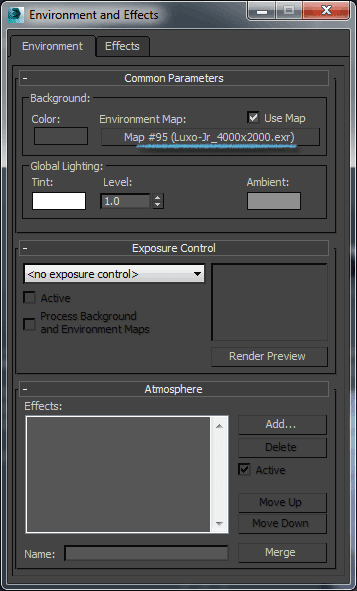
I then dragged and dropped "HDR map" into Environment Map slot. (Press "8" to open the Environment and Effects dialog.)
At this point, I get this render. As expected, the background is now an image.
In case your render is much darker, make sure you enable gamma correction.
Next, I created a Daylight system.
Using a Daylight system means that we need to turn on Exposure Control in Environment and Effects
dialog. I will cover this below. Here are the settings for the Daylight system:
And here are the settings for Exposure Control in Environment and Effects dialog.
Some of the settings above are my attempt to match the lighting in the background image. Matching lighting in this case involves 3 steps:
Finally, I turned on Final Gather (FG).
After all these setups, we are done with our lighting setup. Here is my final render.
The first two steps are identical to the previous method:
We then enable IBL in the "Global Illumination" tab.
Here is the render that I get.
To illustrate, I will use this head model.
 |
| Figure 1. Plain model |
A few words about HDR. HDR stands for "high dynamic range". Dynamic range means the possible range of brightness that an image has.
- Images that we are familiar with, such as JPG files, are said to have a standard or low dynamic range because they are limited to the range of black (brightness value 0.0) to white (brightness value 1.0).
- High dynamic range images (HDR images) have a range beyond 0.0 and 1.0. The brightest pixel, such as lights or the sun, can have a value like 120.48. Much larger than 1.0!
I recommend reading the Wikipedia article on HDR to learn more.
I used the "Luxo Jr" HDRI map provided by Pixar (who kindly put it in public domain). Figure 2 shows how to create a Bitmap map that uses a HDR image file:
- Create a Bitmap map using Material Editor. (Press "M" to open the Material Editor.)
- Make sure to override the image gamma to 1.0.
- Click "Setup" button.
- Make sure "Enable Color Correction" is disabled.
- Set Mapping to "Spherical Environment".
- Set U Tiling to -1.0 to flip the image horizontally.
 |
| Figure 2. Preparing a Bitmap map to be used as the environment map |
 |
| Figure 3. Setting the Bitmap to the Environment Map slot |
 |
| Figure 4. Rendered image after setting the Environment Map |
In case your render is much darker, make sure you enable gamma correction.
 |
| Figure 5. Enabling Gamma Correction |
Next, I created a Daylight system.
 |
| Figure 6. Creating a Daylight system |
Using a Daylight system means that we need to turn on Exposure Control in Environment and Effects
dialog. I will cover this below. Here are the settings for the Daylight system:
- Set Position to "Manual", then move the Daylight to the appropriate position. I used the background image to guide the placement.
- Set Sunlight to "mr Sun" and Skylight to "mr Sky". ("mr" stands for Mental Ray; though I find myself reading them as "mister Sun" and "mister Sky".)
- Set Red/Blue Tint of mr Sun to 0.1.
- This makes the sun color a little yellow.
 |
| Figure 7. Daylight system and its settings |
And here are the settings for Exposure Control in Environment and Effects dialog.
- Drag and drop "HDR map" from Material Editor to Environment Map slot.
- Set Exposure Control to "mr Photographic Exposure Control".
- Set Exposure Value (EV) to 14.125.
- This will make rendered image not overly bright.
- If I set the Exposure Value to 0, the rendered image will by almost totally white because the strong mr Sun overexposes the image.
 |
| Figure 8. Setting Exposure Control |
Some of the settings above are my attempt to match the lighting in the background image. Matching lighting in this case involves 3 steps:
- Placing the Daylight approximately where the sun is in the background image;
- Setting the Exposure Value such that the brightness of the Daylight is similar to the background image;
- Setting the Red/Blue Tint parameter of mr Sun to match how yellow the sunlight is in the background image.
Finally, I turned on Final Gather (FG).
- Check Enable Final Gather.
- Set the three parameters (Initial FG Point Density, Rays per FG Point, and Interpolate Over Num. FG Points) as shown below.
 |
| Figure 9. Enabling Final Gather |
 |
| Figure 10. Rendered image with the HDR lighting |
Bonus: Image-Based Lighting (IBL)
An alternative method is Image-Based Lighting (IBL). IBL is faster to set up (you do not need to match the lighting in the background image), but slower to render.The first two steps are identical to the previous method:
- Create a Bitmap map that uses a HDR image.
- Drag and drop the Bitmap map to the Environment Map slot in "Environment and Effects" dialog.
 |
| Figure 11. Creating a Skylight |
 | |
| Figure 12. Enabling Image-Based Lighting (IBL) |
 |
| Figure 13. Rendered image using IBL |
Sunday, May 17, 2015
Preparing a Job Application part 3 - How to Prepare within a Limited Time
As an instructor at CG Protege, I had a number of occasions helping students preparing a demo reel (as a part of their job applications) within a limited time period. In this article I will cover a planning method I used. Admittedly, the degree of success varies with how discipline a student; but I think this is to be expected.
There are 3 major steps in the planning.
You may ask, "How can I allow myself six weeks before deadline? After all, job application deadline is set by the company." My answer is, "Consider an different point of view. Assign yourself six weeks to finish your reel and apply for jobs with deadline after your estimated finish date." I admit that this is easier to say than to do.
Resist any temptation to go into a specific work file and do fixes. You may we end up spending most of the available time on one work (or two) and practically neglect the rest. We want to avoid this.
Next, you list what improvements or fixes you would like to do on each work (while keep resisting the tendency to fix anything). At this stage you can be as detailed as you want, no restraint yet. Spend up to 15 minutes for each work.
Now that you have considered all the improvements you want to do within the time available, you will realize that you need to prioritize. This is the next step. Create a timeline from today until the deadline. Move items from your improvement list into the timeline based on priority. In this way, you will have a daily plan to cramp in the most important improvements.
Here is a sample template:

Things to look out for:
During such review, compare what you planned to achieve with what you actually achieved. Update your plan for the remaining time accordingly so that you can get as many improvements as time allows. The update can be re-prioritizing to do items, removing to do items, or, very rarely, adding new to do items. You may end up with less than what you planned in the beginning, but you will achieve something better than what you started with.
I hope this simple planning help you.
Let me close this post with my story behind these articles. To you, this is the last part of a three-part article. To me, this is the article I started with. As I wrote this article, I found myself having to explain the details of writing cover letter and resume, as well as demo reel and portfolio. I ended up with a very long blog post. I decided to break them into three. As I fleshed out my outline, the content shifted a little from my original plan. I felt especially the second article felt not as sincere as I intended.
As always, if you any thoughts you want to share, please comment below.
There are 3 major steps in the planning.
The first step is to clarify your goal.
Your goal is to submit an application to a specific company, by a specific date. There are 3 components in this goal: the application, the company, and the deadline.- The application consists of a cover letter, a resume, and a demo reel (+ portfolio).
- The company is interested to see applications relevant to their interest.
- The deadline is important. You do not want to submit your application late.
- Writing a cover letter specifically for the company, explaining why you are the best fit for the job opening;
- Customizing your resume to what the company is asking for;
- Assembling a demo reel (+ portfolio) to show that you have the skills that the company needs; and
- Submitting these to the company before the deadline.
You may ask, "How can I allow myself six weeks before deadline? After all, job application deadline is set by the company." My answer is, "Consider an different point of view. Assign yourself six weeks to finish your reel and apply for jobs with deadline after your estimated finish date." I admit that this is easier to say than to do.
The second step is to plan steps to your goal.
First, you should have a list of works you want to include in your demo reel.Resist any temptation to go into a specific work file and do fixes. You may we end up spending most of the available time on one work (or two) and practically neglect the rest. We want to avoid this.
Next, you list what improvements or fixes you would like to do on each work (while keep resisting the tendency to fix anything). At this stage you can be as detailed as you want, no restraint yet. Spend up to 15 minutes for each work.
Now that you have considered all the improvements you want to do within the time available, you will realize that you need to prioritize. This is the next step. Create a timeline from today until the deadline. Move items from your improvement list into the timeline based on priority. In this way, you will have a daily plan to cramp in the most important improvements.
Here is a sample template:

Things to look out for:
- If you have not rendered your reel, how long does it take to render a frame? How many frames are there in your reel? This sets the latest date you can still improve your 3D work.
- Make sure you have time for rendering as well as fixing render problems.
- Where are you uploading your reel? If you upload your video to YouTube, your video will be available almost instantly after uploading finishes. If you upload your video to Vimeo, your video will be available only around an hour after uploading finishes.
- Make sure you have enough time to make your reel available for viewing.
- Remember to include writing your cover letter and resume in your plan.
- Make sure you have enough time to write an excellent cover letter.
- Make sure you have enough time to customize your resume to the job position.
- How do you submit your application?
- Make sure you have enough time to submit.
The third step is to carry out your plan.
Make sure to review your progress periodically. If your deadline is days away, review at the end of each day. If your deadline is further, you can review once every two days or even weekly.During such review, compare what you planned to achieve with what you actually achieved. Update your plan for the remaining time accordingly so that you can get as many improvements as time allows. The update can be re-prioritizing to do items, removing to do items, or, very rarely, adding new to do items. You may end up with less than what you planned in the beginning, but you will achieve something better than what you started with.
I hope this simple planning help you.
Let me close this post with my story behind these articles. To you, this is the last part of a three-part article. To me, this is the article I started with. As I wrote this article, I found myself having to explain the details of writing cover letter and resume, as well as demo reel and portfolio. I ended up with a very long blog post. I decided to break them into three. As I fleshed out my outline, the content shifted a little from my original plan. I felt especially the second article felt not as sincere as I intended.
As always, if you any thoughts you want to share, please comment below.
Subscribe to:
Posts (Atom)